Groundwater is water that is held in soil, either in a non-saturated or saturated form. The water table is a line showing the change in water content in the soil, below which soil is saturated with water.
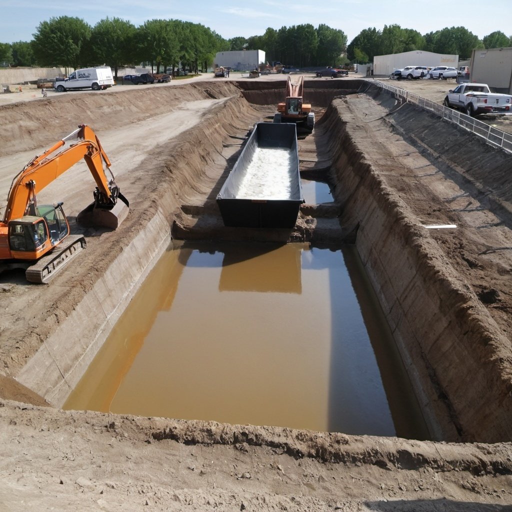
Water in soil often acts as a lubricant. It increases the tendency of soil to slip or slide. Also, it causes certain difficulties and dangers in the case of excavations to be done. In some soil, such as non-cohesive soil with a coarser grain composition, water can flow through the grain particles. Construction of foundations below the subsoil water level poses problems of waterlogging. It is therefore very often necessary to dewater the area of excavation.
Several operations have to be carried out within the excavation, like laying bed concrete, laying of RCC raft slab, and construction of masonry, etc. These works can be carried out more efficiently if the excavation area is kept dry.
Reducing the Water Level below the Excavation Bottom
To keep the excavated area dry, the water table should be maintained at least 0.5 m below the bottom of the excavation. There are several methods available for lowering the water table.
Dewatering for Shallow Foundations
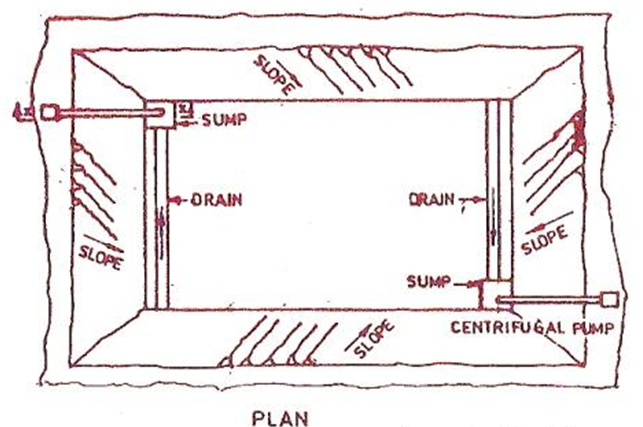
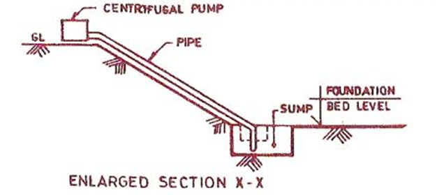
For fairly dense soil and shallow excavations, the simplest method is to have drains along the edges of the excavation, collect water in sumps, and remove it by pumping. This is the most economical method and is feasible for being executed with unskilled labour and simple equipment.
Dewatering for Large Excavations and Deep Foundations
Wellpoint system
Where large excavations such as for rafts are to be dewatered, a wellpoint system can be employed. This is a method of keeping an excavated area dry by intercepting the groundwater flow with pipe wells driven deep into the ground.
Wellpoint consists of a perforated pipe, 120 cm long and 4 cm in diameter with a valve to regulate flow and a screen to prevent entry of mud, etc.
These wellpoints are installed along the periphery of the excavation at the required depth and spaced at about 1m. The exact spacing can be decided based on the type of soil.
The wellpoint tube is connected to a 5 to 7.5 cm diameter pipe known as a riser pipe and is sunk into the ground by jetting. These pipes are connected to a header pipe which is attached to a high capacity suction pump. The groundwater is drawn out by the pumping action and is discharged away from the site of excavation.
In the process of jetting, water is forced down through the wellpoint at the rate of 20 to 25 liters per second. The water jet dislodges the surrounding soil and enables the wellpoint to be sunk to the desired depth. After the wellpoint has been sunk to the required depth, the water jet is allowed to run for some time (to ensure washing all sand or silt ‘out of the hole) till the return water from the hole is quite clean.
Thereafter the water jet is closed and the annular space formed around the wellpoint (by the jetting action of water) is filled with coarse sand and gravel to form a filter zone around the wellpoint. The filter zone prevents the entry of fine particles of the surrounding soil into the wellpoint and avoids clogging the wellpoint screen. The filter sand around the wellpoint should be filled up to the water table. The depth of the hole above the water table is filled with tamped clay to act as a clay seal to minimize air getting into the wellpoint through the sand filter.
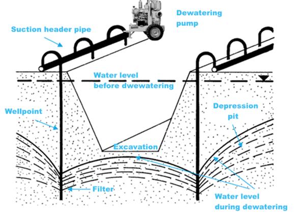
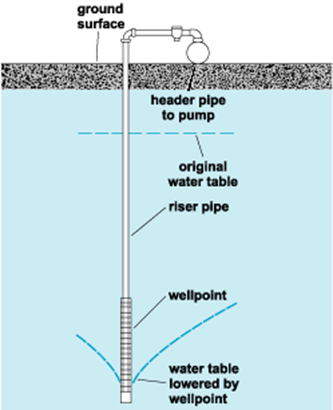
After all the wellpoints are installed and connected, the suction pump is put into operation. Due to suction, the ball valve in the wellpoint gets closed and the groundwater is drawn in through the wellpoint screen. The water from the wellpoint is sucked up through the riser pipes, flows through the header pipe, and is finally discharged away from the worksite.
This method can be successfully adopted for depth of excavation up to 18 m. Since the suction pump is normally not used to lift water above 6 m depth, in’ a deep excavation, where it is necessary to lower the water table to a greater depth, a multi-stage system of wellpoint is used.
Other Methods for Excavation of Foundation in Water Logged Sites
The following methods are generally adopted while digging foundation trenches in water-logged sites.
By constructing deep wells
In coarse soils, porous rock, or in sites where a large quantity of sub-soil water is required to be drained out, 30 to 60 cm diameter wells are sometimes constructed at 6 to 15 m centers all-round the site for temporary drainage of the ground. The water collected in the wells is pumped out continuously. This method can be adopted for depths of excavation up to 24 m.
Freezing Process
This process is suitable for excavations in water-logged soils like sand, gravel, and silt. It is advantageously used for deep excavation such as foundations for bridges, etc. especially when excavation is to be made adjacent to an existing structure or near some waterways.
The process consists of forming a sort of coffer darn by freezing the soil around the area to be excavated. Freezing pipes encasing smaller diameter inner pipes are sunk about one-meter from center to center along the periphery of the area to be excavated. The layout of the pipes should preferably be such that the area enclosed is circular in plan.
Freezing liquid is then supplied to the freezing pipes by the refrigeration plant. These make the ground around the pipes freeze and form a thick wall of frozen earth around the area to be excavated. This process can be used up to 30 m depth of excavation.
Chemical consolidation of soil
In this method, the soft water-logged soil is converted into a semi-solid mass by forcing chemicals like silicates of soda and calcium chloride into the soil. This method is used for small works.
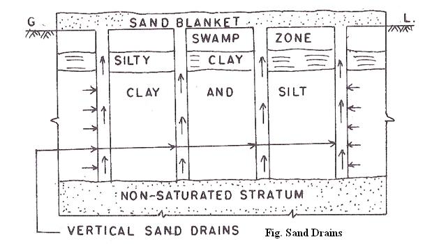
Constructing sand drains
Sand drains prove very effective in marshy soils. Soil becomes marshy by the process of deposition of thick layers of clays and silts mixed with organic matter by the passage of time. Marshy soil is thus subjected to capillarity and has a high pore water pressure. When this type of soil is subjected to load, its wet soil contents are gradually pushed out on either side and this results in subsidence of the ground. To avoid this, sand drains are made in the ground.
The diameter of the sand drains normally varies between 300 mm to 450 mm and their center-to-center spacing may vary from 3 to 6 meters. The hole for making the sand drain can be made by driving steel pipe casting into the ground. The drain holes are driven deeper than the marshy layer possibly up to an underlying rock or firm base. The marsh in the pipes is removed using water jets. Selected type of sand is then filled into the pipes and the pipes are withdrawn leaving vertical sand piles in the ground. A thick layer of sand (sand blanket) is spread over the entire area to be consolidated. When the sand layer is subjected to load, the water from the muck of the marshy soil gets squeezed into the vertical sand drains.

Sand Drains
By capillary action, the water from the sand drains rises and is fed into the sand blanket from where it can be drained out. The objective of consolidation of soil by this method is to develop increased soil resistance to superimposed loads usually consisting of earth fills in highway or airport construction.
Electro-Osmosis
The Wellpoint system is rendered ineffective in very fine sands, silts, or clay because such soils tend to hold the water by capillary action and offer great resistance to percolation. It has been established that if a direct current is passed through a soil of low permeability, its rate of drainage is greatly increased.
In the process of Electro-Osmosis, steel rods forming the positive electrodes are driven into the soil midway between the wellpoints, which are made to act as negative electrodes. When an electric current is passed, the groundwater flows toward the negative electrode (wellpoints) and is pumped out. This requires expensive equipment and hence it is rarely used.
Grouting
Grouting is often used to stop the penetration of water in sub-soil with high permeability, such as in fissured and jointed rock strata. Rows of holes are bored into the soil and, usually cement grout, are injected under high pressure. The cement grout will penetrate the voids of the sub-soil and form a somewhat impermeable curtain vertically separating the groundwater.
Cement grout is usually a mixture of cement and water, or cement and sand under a ratio maximum 1:4. Sometimes chemical grout can be used to form a gel which can increase strength and reduce permeability of soil. (e.g. Sodium silicate + calcium chloride = calcium silicate, which is a silica gel).