The traditional meaning of Primary treatment implies a sedimentation process to separate the readily settleable and floatable solids from the wastewater.
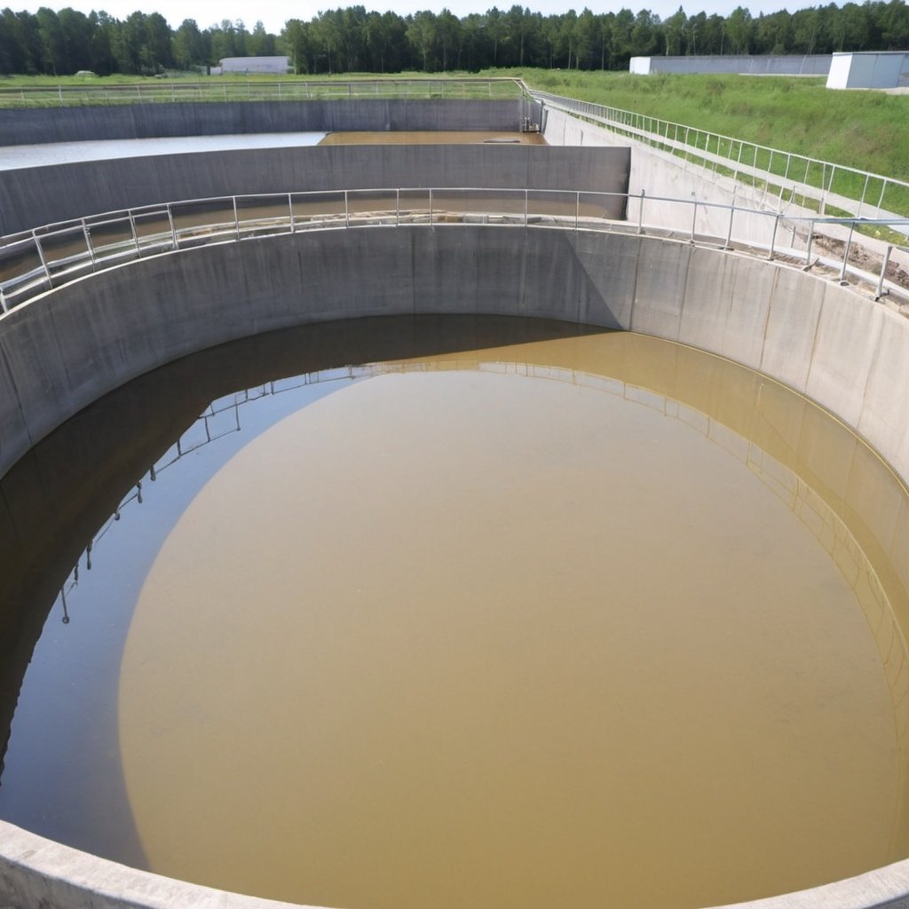
The treatment unit used to settle raw wastewater is termed the primary sedimentation tank (basin), primary tank (basin), or primary clarifier.
Sedimentation is the oldest and most widely used process in the successful treatment of wastewater.
After the wastewater passes the screens, comminutors, and grit chambers, the wastewater enters sedimentation tanks.
The suspended solids that are lighter than solids that fell out into the grit chamber will settle in the tank over a few hours.
The settled sludge is then removed using mechanical scrapers or pumped.
Surface skimmer devices are used to remove floatable substances on the tank surface.
Then, the effluent flows to the secondary treatment units or is discharged.
The flow velocity of wastewater in primary sedimentation tanks is reduced by plain sedimentation.
The process usually removes particles with a settling rate of 0.3 to 0.6 mm/s.
In some cases, chemicals also may be added.
Reduced suspended solids content, equalization of side stream flow, and BOD removal are the benefits of the primary sedimentation process.
The overflow rate of the primary sedimentation tanks ranges from 24.5 to 49 m3/(m2-d).
Usually, the detention time in these tanks is 1-3 hours.
Primary tanks (or primary clarifiers) remove 90-95 percent of settleable solids, 50-60 percent of total suspended solids, and 25-35 percent of the BOD5.
Type 2 flocculent settlings are the usual settling characteristics in the primary clarifier.
Due to the continuous changes in the shape, size, and specific gravity of flocculated particles, Stoke’s formula for settling velocity cannot be used to determine particle settlement.
Due to these reasons, no mathematical equation can be used to describe flocculent settling satisfactorily. Therefore, laboratory analyses such as settling-column tests are commonly used to generate design information.
RECTANGULAR BASIN DESIGN
Usually, multiple units with common walls are designed and constructed for independent operations. Basin dimensions are designed based on the surface overflow (settling) rate to calculate the required basin surface area.
The required area of the sedimentation tank is equal to the flow divided by the selected overflow rate.
An overflow rate of 36 m3/(m2•d) at average design flow is generally acceptable.
Basin surface dimensions, the length (l) to width (w) ratio (l/w), can be increased or decreased without changing the volume of the basin.
For a greater l/w ratio, the basin has a proportionally larger effective settling zone and a smaller percentage of inlet and outlet zones.
Increased basin length allows the development of a more stable flow.
The inlet structures in rectangular clarifiers are placed at one end and are designed to disperse the inlet velocity to diffuse the flow equally across the entire cross-section of the basin and to prevent short-circuiting. Typical inlets consist of small pipes with upward ells, perforated baffles, multiple ports discharging against baffles, a single pipe turned back to discharge against the headwall, simple weirs, submerged weirs sloping upward to a horizontal baffle, etc.
The inlet structure should be designed in such a way as not to trap scum or settling solids.
Baffles are installed 0.6 to 0.9 m in front of inlets to assist in diffusing the flow and submerged 0.45-0.60 m with a 5 cm water depth above the baffle to permit floating material to pass.
Scum baffles are placed in front of outlet weirs to hold back floating material from the basin effluent. These extend 15-30 cm below the water surface.
Outlets in a rectangular basin consist of weirs located toward the discharge end of the basin.
Walls of settling tanks should extend at least 150 mm above the surrounding ground surface and shall provide not less than 300 mm freeboard.
Mechanical sludge collection and withdrawal facilities are usually designed to ensure rapid removal of the settled solids.
The minimum slope of the side wall of the sludge hopper is 1.7 vertical to 1 horizontal.
The hopper bottom dimension should not exceed 600 mm.
The sludge withdrawal line is at least 150 mm in diameter and has a static head of 760 mm or greater with a velocity of 0.9 m/s.
CIRCULAR BASIN DESIGN
Inlets in circular or square basins are typically at the center and the flow is directed upward through a baffle that channels the wastewater (influent) toward the periphery of the tank.
Inlet baffles are 10-20 % of the basin diameter and extend 0.9-1.8 m below the wastewater surface.
The degree of turbulence in circular basins is higher when compared to rectangular basins. Therefore, circular basins are more efficient as flocculators.
A typical depth of the sidewall of a circular tank is 3 m.
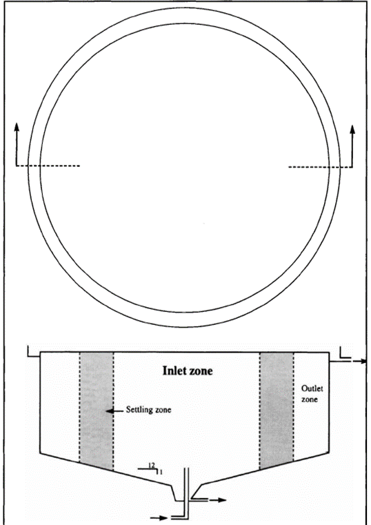
As shown in Figure, the floor slope of the tank is typically 300 mm horizontal to 25 mm vertical.
Outlet weirs extend around the periphery of the tank with baffles extending 200-300 mm below the wastewater surface to retain floating material. Overflow weirs shall be located to optimum actual hydraulic detention time & minimize short-circuiting.
Peripheral weirs shall be placed at least 30 mm from the well.