Introduction
Excavation means to loosen and take out materials, leaving space above or below ground. In civil engineering, earthwork includes backfilling with new or original materials to voids, spreading, and leveling over an area.
The content of the excavation proposal should include the following information:
1. Detail of method for ground protection treatment and dewatering.
2. Survey of existing site condition
2.1 accurate level survey
2.2 geotechnical survey
2.3 ground and surface water information
2.4 record/report of the surrounding facilities and structures
3. Detail design or construction proposal regarding:
3.1 site/soil investigation report and geotechnical assumptions
3.2 detail of excavation/protection works
3.3 sequence and method of works
3.4 monitoring proposal
EXCAVATION
Excavation in most situations is done by mechanical means. However, the exact method to be adopted still depends upon several factors:
1. Nature of subsoil – affects the type of machine used and the necessity of soil protection.
2. Size of excavation – affects the type of machine used and excavation method.
3. Scale of work – a large volume of excavation may involve complicated phasing arrangement and work planning
4. Ground water condition – affects the degree of protection (watertight sheet piling or dewatering may be required.)
5. Surrounding condition – impose certain restrictions and precautions (e.g. diversion of a drain, or underpinning work to the nearby building foundation)
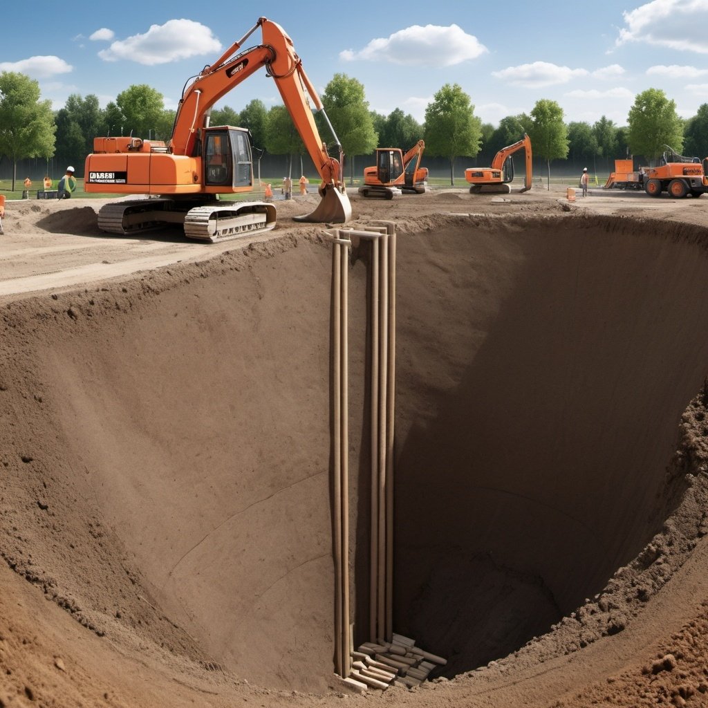
Deep excavation
Deep excavation, unlike a shallow one, often requires protecting the sides of the cut using suitable support. Besides, the problem of groundwater cannot be avoided. There are methods to overcome this, such as:
1. Dumpling method
This is used where there are buildings or streets in the proximity. The method is to construct a series of retaining walls in a trench, section by section, around the site perimeter, leaving a center called a “dumpling”.
When the perimeter walls are in place, excavation may start at the center of the dumpling, until exposing a section of the wall. Then the wall may be side supported by struts, shoring, soil anchors, etc., again section by section in short lengths, until the excavation is all completed.
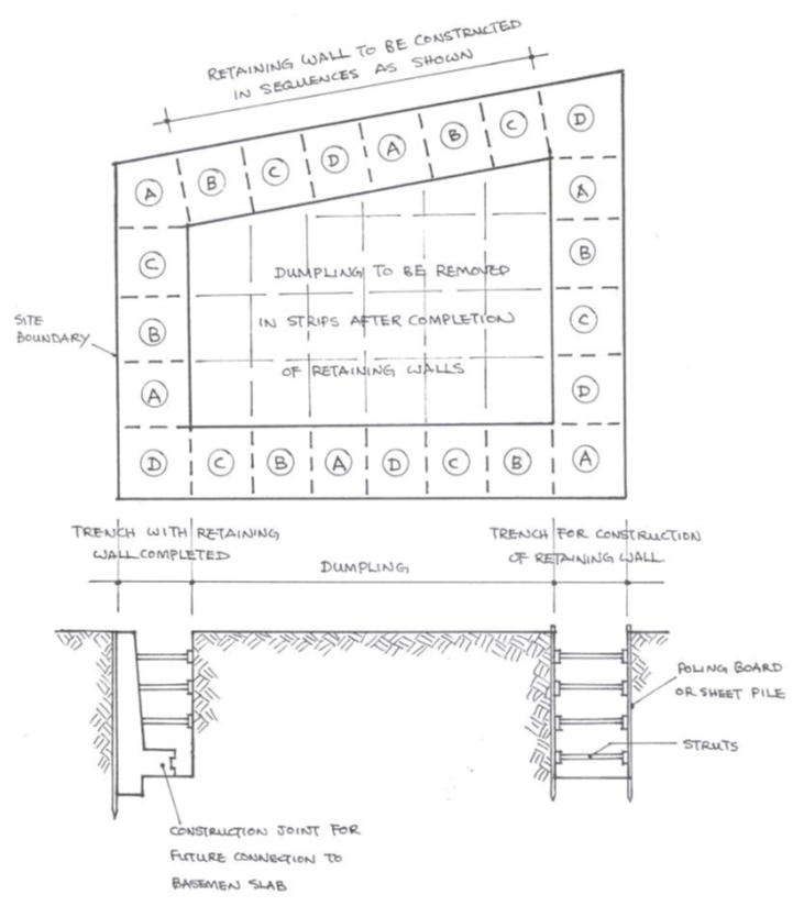
Excavation and Construction of Shallow Basement using Dumpling Method
This method does not require much heavy mechanical equipment and thus cost of work is relatively lower. It can excavate up to a maximum depth of about 3m. Sometimes in very poor soil or waterlogged ground, interlocking steel sheet piles may be driven to confine the area to be excavated. After that excavation can be done in sections and properly supported similar to that mentioned above. By the use of sheet piles, excavation may reach a maximum of about 15m. However, the cost of work will be increased.
2. Diaphragm walling
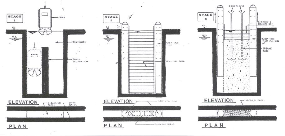
Construction sequence of Diaphragm Wall
This method needs to construct a Reinforced Concrete retaining wall along the area of work. Because the wall is designed to reach a very great depth, a mechanical excavating method is employed. A typical sequence of work includes:
a) Construct a guide wall
b) Excavation for the diaphragm wall
c) Excavation support using Bentonite slurry
d) Insert reinforcement and concreting
Construct a guide wall – A guide wall is two parallel concrete beams running as a guide to the clamshell which is used for the excavation of the diaphragm wall.
Excavation for the diaphragm wall – In normal soil conditions excavation is done using a clamshell or grab suspended by cables to a crane. The grab can easily chisel boulders in soil due to its weight.
Excavation support – excavation for the diaphragm wall produces a vertical strip in soil which can collapse easily. Bentonite slurry is used to protect the sides of the soil. Bentonite is a naturally occurring clay which, when added to water, forms an impervious cake-like slurry with large viscosity. The slurry will produce a great lateral pressure sufficient enough to retain the vertical soil.
Reinforcement – reinforcements are inserted in the form of a steel cage, but may require to lap and extend to the required length.
Concreting – concreting is done using Tremie. As Concrete is being poured down, Bentonite will be displaced due to its density being lower than concrete. Bentonite is then collected and reused. Usually, compaction for concrete is not required for the weight of the Bentonite will drive most of the air voids in concrete.
Joining design for the diaphragm wall – Diaphragm walling cannot be constructed continually for a very long section due to tremendous soil pressure. The wall is usually constructed in alternative sections. Two stop-end tubes will be placed at the ends of the excavated trench before concreting. The tubes are withdrawn at the same time as concreting so that a semi-circular end section is formed. Wall sections of this type are built alternatively leaving an intermediate section in between. The interior sections are built similarly but without the end tube. At the end, a continual diaphragm wall is constructed with the sections tightly joined by the semi-circular groove.
Using cofferdams
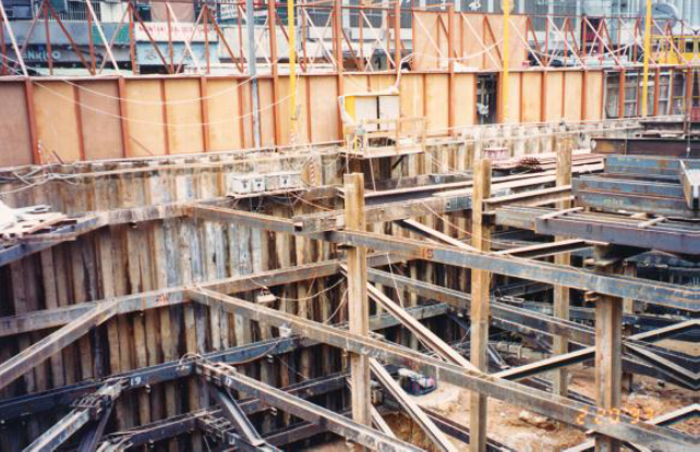
Making use of sheet pile to form a cofferdam to support excavation
A cofferdam may be defined as a temporary box structure constructed in earth or water to exclude soil or water from a construction area, such as for foundation or basement works.
Use of cofferdam suitable for excavation of larger scale can be of:
a) Sheet pile cofferdam – Also known as single skin cofferdam. Interlocking type steel sheet pile is used and can be used for excavation up to 15m. Sheet pile in this case acts as a cantilever member to support the soil therefore adequate depth of pile or suitable toe treatment may be required. In addition, cofferdams need to be braced and strutted or anchored using tie rods or ground anchors.
b) Double-skin cofferdam – This works similarly to the sheet pile to form a diaphragm. However, the diaphragm is double-skinned using two parallel rows of sheet piles with a filling material placed in the void between. This creates somewhat a gravity-retaining structure and increases the ability to counteract the soil behind. However, more working space is required.
Sheet Steel Piling
Steel, amongst other materials such as timber, is most effective to be used as a sheet pile due to its high tensile as well as its interlocking ability. It can be used as timbering to excavation in soft and/or waterlogged soils, especially in a congested site where there is not enough space for complicated shoring.
Steel sheet piles can be of numerous shapes, thicknesses, and sizes. Most of them can be water-tight and for some heavy sections, they can be driven down to 15m depth. To erect and install a series of sheet piles and keep them vertical in all directions a guide frame may be required. The piles are lifted by a crane, using the lifting holes near the top of each pile, and positioning them between the guide walling of the guide. A Powered hammer (fitted with a grip to the pile) which is hung by the crane is usually used to drive the pile. Sometimes hydraulic hammers can be used to reduce noise.
There is a tendency for the piles to lean in a direction during driving. Special control is therefore required to monitor the pile is vertical all the way through.
Ground anchor
A Ground anchor is a pre-stressing tendon embedded and anchored into soil or rock to provide resistance to structural movements by a “tying back” principle.
Common applications are:
1. General slope stabilization
2. Tying back/stabilizing a retaining structure
3. Tying back/stabilizing for diaphragm walls, but for a temporary nature during excavation
4. Tying back the entire building from possible uplifting
Ground anchors can be classified into:
1. Rock anchor – for anchorage in rock
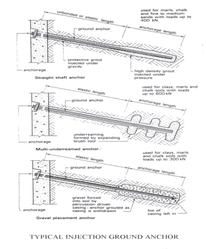
2. Injection anchor – suitable for most cohesive and non-cohesive soils
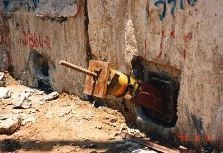
Method to form a ground anchor
A hole is predrilled on soil or rock in a position carefully calculated. For rock anchors, an anchor bar with expanded sleeves at the end is inserted into the hole. A dense, high-strength grout is injected over a required length to develop sufficient resistance to hold the bar when it is stressed. Stressing is by hydraulic means and when the stress is developed, the head of the bar is held by an end plate and nut.
For injection anchors, a hole should be bored usually with an expanded end to increase anchorage ability. The pre-stressing bar is placed into the borehole and pressure grouted over the anchorage length.
It should be noted that certain protection measure against corrosion or rusting is required for the stressing bar. Usually, the bar may be coated with bitumen, wrapped by greased tape, or filled with non-pressurized grout after stressing is completed.
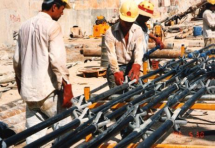
The tendon (steel rod) for tying the anchor before inserting it into the borehole